AGENDA - PC BOARD EMC DESIGN PRACTICES
 There has been significant evolution in power and signal distribution technology since the point to point schemes used in the wiring of vacuum tube and early transistor based circuits. Power voltages have plummeted with corresponding increases in current along with over 3 orders of magnitude increase in signal speeds (frequency). In many cases PCB component dimensions are greater than the harmonic wavelengths of the signal being propagated on the board. As an example, the propagation wavelength of the 9th harmonic of a 3 GHz cpu clock in a PCB with a dielectric constant of 5 is only 0.2 inches. PCB technology has permitted automated circuit manufacturing and uniformity, but the increased currents, higher speeds, and smaller board dimensions of today make PCB design for EMC a definite challenge.
EMC problems in digital systems are linked directly to active components on printed circuit boards. This course will explore PCB design practices to reduce RF emission and susceptibility (immunity). Analog and digital PCBs will both be discussed, but EMC design practices for high-speed logic circuits requiring transmission line techniques will be emphasized. Presentation format will be independent of the logic families that may be employed. RF sources, victims and coupling paths will be identified. PCB power distribution; the effect of propagation delay; standing waves; transmission line characteristics: crosstalk from interconnect traces; radiated emission from chips, interconnects, and cables; radiated susceptibility of circuits; and design techniques for mainataining signal integrity while resolving EMC problems will be discussed.
1. LOGIC CHARACTERISTICS
2. RF RADIATION TO/FROM DEVICES AND INTERCONNECTS
3. GENERAL LAYOUT OF PRINTED CIRCUIT BOARDS
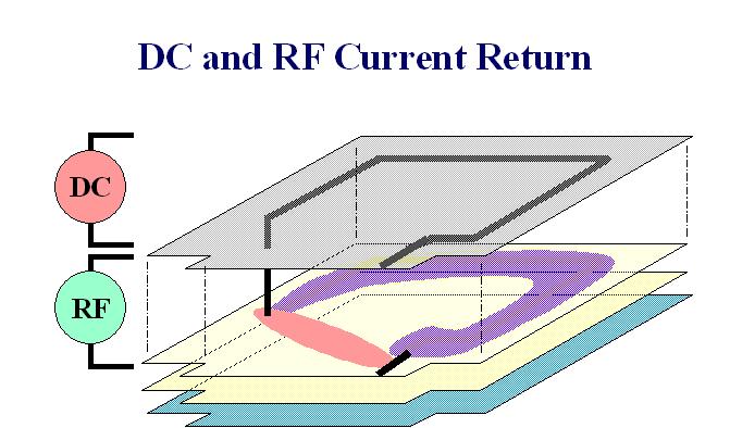
4. POWER DISTRIBUTION
5. SIGNAL DISTRIBUTION
6. CROSSTALK AND TRACE-TO-TRACE COUPLING
7. PCB AND CIRCUIT SHIELDING
www.ronbrewer.com